Описание
Компания реализует по цене от производителя концевой выключатель КУ-701.
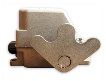
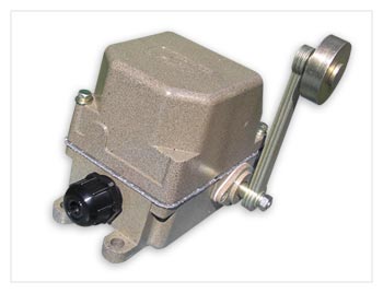
Корпус концевого выключателя КУ-701 выполнен из материала АК-12 (это позволяет выключателям работать в агрессивной среде, не испытывая при этом ни малейшего дискомфорта) литьем под высоким давлением в брызгозащитном исполнении. При установке на открытом воздухе рекомендуется защищать выключатели от воздействия атмосферных осадков.
Назначение
Концевой выключатель КУ-701 предназначен для включения и выключения цепей управления механизмов и применяются в качестве путевых. Климатические исполнения — У, ХЛ, Т. Категория размещения — 2.
Устройство и принцип действия концевого выключателя ку-701
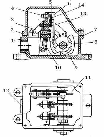
Внутри корпуса (1) закреплен вал (8) на котором находятся кулачковые шайбы (9), храповик (11) , а снаружи выключателя на валу закрепляется ручаг привода. Движение храповика ограничивает фиксирующий механизм (5) усилие которого контролируется пружиной (10).
Следующий важный узел выключателя КУ-701 — это блок контактов. Он состоит из изоляционной клемной колодки (6) на которой крепятся неподвижные контакты (4), два рычага (13) с контактными мостиками подвижных контактов (5). На поверхности медных контактов нанесен слой технического серебра, что повышает срок службы выключателя.
Устройство концевого выключателя ку-701
Механизм выключателя защищен от воздействия агрессивной среды крышкой (2) герметичное соединение которой с корпусом обеспечивает уплотняющая прокладка (7).
Пружины удерживают контакты в замкнутом состоянии. При отклонении рычага выключателя КУ-701 от нормального положения, вал поворачивается и выступы на кулачковых шайбах оказывают давление на выступ рычаг на котором закреплен мостик подвижных контактов. Рычаг поворачивается, происходит разрыв цепи главного тока или тока управления.
Концевые выключатели КУ-701 допускают любой порядок замыкания контактов. Этот порядок регулируется кулачковыми шайбами положение которых на валу можно изменить.
Допустимые токовые нагрузки
- Ток продолжительного режима: 10А;
- Включаемый переменный ток (напряжение до 500В): 50А;
- Включаемый постоянный ток (напряжение до 110, 220, 440В): 25А;
- Отключаемый переменный ток (напряжение до 500В): 10А;
- Отключаемый постоянный ток (напряжение до 110, 220, 440В): 2,0/1,5/0,5.
Характеристики
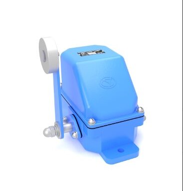
| Тип привода: | рычаг с роликом |
| Фиксация: | самовозврат рычага |
| Количество возможных положений рычага: | 3 |
| Количество устойчивых положений рычага: | 1 (нулевое) |
| Число электрических цепей: | 2 |
Тип привода концевых выключателей КУ-701, КУ-703, КУ-704
| Наименование | Тип привода | Фиксация |
| КУ-701 A | Рычаг с роликом | Самовозврат рычага |
| КУ-703 А | Груз с противовесом | Фиксация в крайних положениях |
| КУ-704 А | Рычаг пластинчатый W-образный | Фиксация в каждом положении |
Технические данные
Концевые выключатели КУ-700 имеют две независимые электрические цепи и могут работать как на постоянном, так и на переменном токе. Допустимая токовая нагрузка приведена в таблице ниже.
| Сила тока продолжительного режима, А | Сила включаемого тока, А | Сила отключаемого тока, А | ||
| переменный, напряжение до 500 В | постоянный, напряжение 110, 220 440 В | переменный, напряжение до 500 В | постоянный, напряжение 110, 220, 440 В | |
| 10 | 50 | 25 | 10 | 2,5; 1,5; 0,5 |
Устройство и работа
Все выключатели унифицированы и отличаются только приводом. Выключатель состоит из корпуса и крышки, выполненных литыми из алюминиевого сплава, кулачкового барабана с кулачковыми шайбами и фиксирующего механизма (кроме выключателя КУ-703).
В выключателях КУ-701 храповик под действием пружины фиксирует рычаг в нулевом положении.
Размещение и монтаж
Концевые выключатели КУ-700 могут быть установлены в любом положении.
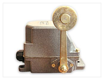
Рычаг на выключателях КУ-700 устанавливается в различных положениях относительно корпуса. Для перестановки рычага на 90° по часовой стрелке относительно вала снимите рычаг, поверните его на 90° по часовой стрелке, не поворачивая вала, и закрепите на валу.
Для получения нужной схемы замыкания производите переборку выключателя в следующем порядке: извлеките барабан из корпуса, отверните гайку барабана, снимите кулачковые шайбы с вала и расположите их на валу согласно выбранной схеме, затем соберите выключатель.
Выключатели должны быть заземлены. В выключателях исполнения Т предусмотрены заземляющие болты, для исполнения У — зачищенная поверхность одной из лап. Перед осмотром выключатель отключите от сети.
Проверив правильность установки выключателя, приводной линейки или штыря, а также схемы, можно переходить к опробованию срабатывания выключателя посредством механизма.
Перед опробованием необходимо убедиться в надежности тормозов и наличии упоров в механизме.
Опробование начинайте с малых скоростей движения приводной линейки, постепенно переходя к полным скоростям.
Возможные неисправности и методы их устранения
| НЕИСПРАВНОСТЬ | ПРИЧИНА | МЕТОД УСТРАНЕНИЯ |
| Чрезмерное повышение температуры контактов | а) слабое нажатие | а) замените пружину кулачкового элемента |
| б) нагар на поверхности контактов | б) зачистите контакты, износившиеся замените | |
| Не возвращается рычаг провода | а) слабая пружина фиксатора | а) замените пружину |
| б) заедание вала в подшипниках | б) смажьте или замените подшипник, устраните несоосность |
Доставка на склад покупателя в любой регион Украины.
Цена: Ценy уточняйте
The company sells the KU-701 limit switch at the manufacturer’s price.
The body of the KU-701 limit switch is made of AK-12 material (this allows the switches to operate in aggressive environments without experiencing the slightest discomfort) by high-pressure casting in a splash-proof design. When installed outdoors, it is recommended to protect the switches from atmospheric precipitation.
Purpose
The KU-701 limit switch is designed to turn on and off the control circuits of mechanisms and is used as a travel switch. Climatic versions — U, XL, T. Placement category — 2.
Design and principle of operation of the KU-701 limit switch
Inside the housing (1) there is a shaft (8) with cam washers (9) and a ratchet (11), and outside the switch there is a drive lever attached to the shaft. The movement of the ratchet is limited by a locking mechanism (5), the force of which is controlled by a spring (10).
The next important component of the KU-701 switch is the contact block. It consists of an insulating terminal block (6) to which fixed contacts (4) are attached, two levers (13) with contact bridges for movable contacts (5). A layer of technical silver is applied to the surface of the copper contacts, which increases the service life of the switch.
KU-701 limit switch device
The switch mechanism is protected from aggressive environments by a cover (2), which is sealed to the body by a gasket (7).
Springs hold the contacts in the closed position. When the KU-701 switch lever is deflected from its normal position, the shaft rotates and the projections on the cam washers exert pressure on the lever projection to which the movable contact bridge is attached. The lever rotates, breaking the main current or control current circuit.
KU-701 limit switches allow any order of contact closure. This order is regulated by cam washers, the position of which on the shaft can be changed.
Permissible current loads
- Continuous current: 10A;
- Switchable alternating current (voltage up to 500V): 50A;
- Switchable direct current (voltage up to 110, 220, 440V): 25A;
- Switchable alternating current (voltage up to 500V): 10A;
- Switchable direct current (voltage up to 110, 220, 440V): 2.0/1.5/0.5.
Characteristics
| Drive type: | lever with roller |
| Fixing: | self-returning lever |
| Number of possible lever positions: | 3 |
| Number of stable lever positions: | 1 (zero) |
| Number of electrical circuits: | 2 |
Type of limit switch drive KU-701, KU-703, KU-704
| Name | Drive type | Locking |
| KU-701 A | Lever with roller | Self-returning lever |
| KU-703 A | Counterweight load | Fixation in extreme positions |
| KU-704 A | W-shaped plate lever | Fixation in each position |
Technical data
KU-700 limit switches have two independent electrical circuits and can operate on both direct and alternating current. The permissible current load is shown in the table below.
| Continuous current rating, A | Inrush current rating, A | Shunt current rating, A | ||
| AC, voltage up to 500 V | DC, voltage 110, 220, 440V | AC, voltage up to 500 V | DC, voltage 110, 220, 440 V | |
| 10 | 50 | 25 | 10 | 2,5; 1,5; 0,5 |
Design and operation
All switches are standardized and differ only in their drive mechanism. The switch consists of a housing and cover made of cast aluminum alloy, a cam drum with cam washers, and a locking mechanism (except for the KU-703 switch).
In KU-701 switches, a ratchet spring locks the lever in the zero position.
Placement and installation
KU-700 limit switches can be installed in any position.
The lever on KU-700 switches can be installed in various positions relative to the body. To reposition the lever 90° clockwise relative to the shaft, remove the lever, turn it 90° clockwise without turning the shaft, and secure it on the shaft.
To obtain the desired closing circuit, reassemble the switch in the following order: remove the drum from the housing, unscrew the drum nut, remove the cam washers from the shaft and place them on the shaft according to the selected circuit, then reassemble the switch.
The switches must be grounded. T-type switches are equipped with grounding bolts, while U-type switches have a stripped surface on one of the legs. Disconnect the switch from the power supply before inspection.
After checking the correct installation of the switch, drive bar or pin, as well as the diagram, you can proceed to testing the switch operation using the mechanism.
Before testing, make sure that the brakes are reliable and that there are stops in the mechanism.
Start testing at low speeds of the drive bar, gradually moving to full speeds.
Possible malfunctions and methods of elimination
| MALFUNCTION | CAUSE | METHOD OF ELIMINATION |
| Excessive temperature rise of contacts | а) weak pressure | a) replace the cam element spring |
| b) carbon deposits on the contact surfaces | b) clean the contacts, replace worn ones | |
| The wire lever does not return | a) weak locking spring | a) replace the spring |
| b) shaft jamming in the bearings | b) lubricate or replace the bearing, eliminate misalignment |
Delivery to the buyer’s warehouse in any region of Ukraine.
Price: Please check the price